3. Infrared Distance Sensor
3.1. Introduction
The infrared distance sensor is designed based on the time of flight (TOF) principle. That is, the sensor emits modulated near-infrared light, which is reflected when it strikes an object. The sensor then calculates the distance to the object by calculating the time difference or phase difference between light emission and reflection.
3.2. Product features
The detection area of the infrared distance sensor is shown in the figure below:
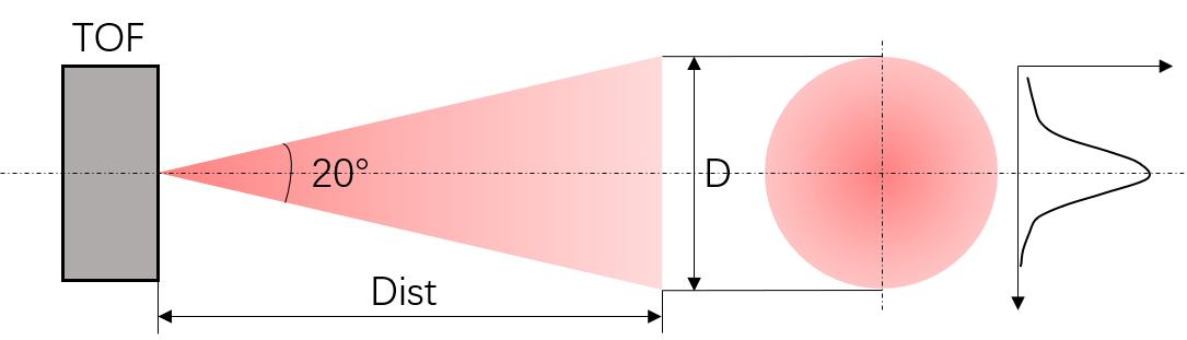
The sensor emits a conical light with an angle of 20°. The relationship between the spot (D) and the distance (Dist) is calculated as follows:
D=2×Dist×tan(10)
To achieve optimal test results, the size of the target must at least equal the size of the TOF spot.
Tip
If the size of the target is smaller than the spot size, ensure that the target is in the center of the spot as far as possible because the light intensity distribution in the spot is not uniform, but a Gauss-like distribution. Specifically, the light intensity is strong in the center and weaker around the edges. For this reason, to ensure sufficient reflected light energy, the target must be in the center of the light spot as far as possible.

3.4. Communication protocol and data format
Control command input:
-
ir_distance_sensor_measure_on¶ Description: Enables data output by the infrared distance sensor, at the output frequency of 20 Hz.
-
ir_distance_sensor_measure_off¶ Description: Disables data output by the infrared distance sensor.
Data output:
-
ir distance:xxx Description: Data format of the infrared distance sensor
Tip
Commands are input and output in the form of strings.
3.5. Python API
Refer to Infrared Distance Sensor.